Many people are asking how difficult our DIY projects are. Let us share skintagain's feedback:
I’ve recently started the assembly of the Pokornyi LMP Pro wheel and thought others may be interested. This post concentrates on the electronics assembly, but if enough people are interested I will gladly continue with the other aspects of the build. I hope to a) give an overview of the build process itself, b.) give people confidence in their ability to do it themselves and c) give tips on where I went wrong or things I found out.
For those that don’t know you can buy a build guide for this wheel from his website.
What is it:
When you buy the guide you get a 38 page (it's 44 page since then) PDF detailing how to assemble and also where and how to order parts. You also get CAD drawings of the 3D printed and machined parts, a bill of materials (what you need to order and quantities), the firmware for the wheel and even the digital artwork for the buttons. I'll admit that when you initially open the document pack that it's quite overwhelming. /u/pokornyib has obviously spent a crazy amount of time and effort, not only going through countless iterations, but offering amazing documentation and detailed guides on each element of the process. For this reason I will not share any CAD drawings or other elements from the pack - so please don't ask.
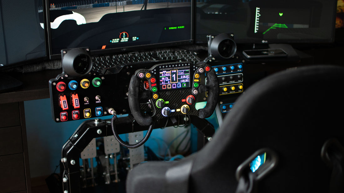
The built wheel itself measures 280mm x 174mm and includes:
- Full carbon fibre composite structure.
- 3" Nextion Display OR VoCore Screen - controlled by SimHub - and usable in most sims.
- 10 x backlit digital buttons on wheel face (9 active in game as 1 is used for integrated wheel functions such as clutch calibration and backlight brightness).
- 2 x magnetic paddle shifts.
- 2 x Clutch paddles - configurables as adjustables dual-clutch, analog or digital with adjustable bite point.
- 16 x Programmable RGB LEDs - controlled also by SimHub.
- 4 x backlit pushable rotary encoders on wheel face - 20 or 12 position variants.
- 2 x shoulder mounted rotary encoders - 20 or 12 position variants.
- Compatible with any 50 or 70mm quick release adapter.
My Experience:
To give you an idea of my skill level - I am a software developer who has previously tinkered with electronics. I can tell you the difference between a capacitor and a resistor but i'm no electrical engineer. I have built simple button boxes in the past and have messed around with SimHub and Arduinos but nothing on this scale.
Electrical Assembly:
For each step of the build I'll also try to objectively rank difficulty. My scale is as follows:
- My mum could do this one handed
- Walk in the park
- Slightly taxing
- I need to concentrate for this
- I'm getting nervous and feel out of my depth
The document pack includes all of the Gerber files necessary to have your PCBs manufactured with two of the biggest manufacturers: JLCPCB.com and PCBWay.com. All files in the pack are named ready for each manufacturer. I chose JLPCB - as the documentation seemed more explicit for them. The process was no harder than sending digital photos to print. I uploaded the files and the only small issue I had was part availability for one of the chips - the build guide even gives guidance on alternatives ICs when this happens. As a final fallback - the pack even contained an altered set of Gerber files if those alternatives are unavailable. I should point out here that you have the cheaper option of just making the PCB without any surface mount components fitted. Unless you are a trained electronic engineer do NOT do this. You will need a commercial soldering station to mount tiny ICs onto a board and it will take you weeks. JLPCB do this for you, and will even continuity test that every item was correctly soldered. The main caveat of this is you need to order a minimum 5 boards - but it's always good to have spares or get a friend to build another. Delivery to the UK took approximately 8 days. - Ordering difficulty rating 1 - My mum could do this one handed.
The boards that you receive from JLPCB contain all of the small surface mount electronics components. They do no include any of the 'through hole' parts e.g. headers, buttons and rotary encoders. These can all be found cheaply online (and are listed in the BOM), but it does require you to solder them on yourself. For this you will need a soldering iron (adjustable temperate is preferable) with a fine tip and a steady hand. In total you are soldering about 80 terminals - but they are all relatively large and thankfully distanced well from the small surface mount components already on the board. Extra points if you have a multimeter to test your joints as you connect them. This isn't essential as as links are provided to joystick test software in Windows. - Soldering difficulty rating 3 - Slightly taxing.
Each of the components that aren't mounted directly to the PCB use molex connectors. This allows you to connect the paddles, display and USB cables with removable connectors onto the headers you previously soldered to the PCB. These are tiny little (1.84mm pitch) pins you must crimp onto hand cut cable - so you'll need cutters, strippers, wire and a pair of crimps designed for the molex connectors. You will need a steady hand, a well lit room and your glasses to do this. They can be a little frustrating because they are so fiddly and your own hands get in the way. My first 5 crimp attempts didn't work - but a proper youtube guide on crimping and 10 test crimps later it becomes much easier. Crimping difficulty rating - 4 falling to 3 with practice.
Once your board is fully assembled you will need to program it. The first part of this is to upload the firmware provided in the document pack. This is done via a ST-Link v2 programmer you can but on eBay for about £30. Unfortunately mine arrived not working so I spent 24 hours scratching my head and trying different PCs. In the end I ordered the cheaper £12 clone from eBay. The documentation mentions that these can be hit or miss. Mine also came with a different wiring configuration to what was mentioned in the build guide - but it's a simple as matching names on the programmer to labels on the PCB. Once connected the upload completed in 30 seconds and the wheel came to life. - Difficulty rating 2 - Walk in the park
For those interested the wheel PCB actually has an integrated USB Hub. This means that the Joystick adapter, SimHub control for the RGB, Serial Port (for Nextion) and an additional USB port for VoCore screens are all connected and powered by a single USB cable to your PC. Once these are all available you can use SimHub to customise the LEDs for game state e.g. colours / patterns based on flags or revs. You can additional use Dash Studio or Nextion Editor to customise your display. This setup supports most common sims include ACC, F1 2020, Dirt 4, PC2 and RF2. It should be noted that the free version of SimHub is limited in frame rate when refreshing the wheel. Difficulty rating 2 - but there is almost unlimited potential to spend days deciding on a dash / light configuration.
The video from this post is the result of the steps performed above - although I hadn't receive my rotary encoders at the time of recording so them are missing from the board.
My Tips:
My main tip would be to read the build guide. And when you think you have understood it, read it again twice. The first read is daunting, there is a lot to take in. On several occasions I couldn't find information I needed, even composing an email draft to ask - but reading again I found the information that I needed.
I would also say take your time and enjoy the build. I've had to intentionally slow myself down. Don't go crazy ordering all the parts at once. It will cost you more and you will probably end up with incorrect parts to return. The BOM is very precise talking about part numbers and dimensions - use these, research them and shop around. Be organised and keep a spreadsheet of what you ordered and from who. Some of the other parts may be coming from China and take two weeks - so don't order all your screws on Prime in a rush. If you are waiting on parts then practice crimping some cables - so that your build will look it's best.
My final tip would be to invest is a "spare pair of hands" - they can be found cheaply on eBay but allow you to hold a part whilst you solder.
Summary:
So far the assembly of the PCB - arguably the most problem prone part has gone smoothly. The 3D printed parts arrived today and the carbon fibre arrives on Monday. I hope to have a fully operation wheel by next weekend. I have genuinely enjoyed the first part to the point my wife has even agreed to hand stitch the suede handgrips for me!
So a big thank you to /u/pokornyib for his time and skill. And to others attemping the build, enjoy!
Source: Reddit - skintagain
Thank you for the feedback!
2 comments
Bonjour, avez vous résolu le problème, car j’ai le même problème ?
tout les soudures et continuité a été vérifiée.
merci.
bonjour, je viens d’acquérir un volant pokornyi LMP PRO d’un amis, qui est passer sur le F1 PRO, qui sera surement mon futur projet. mon problème est le suivant, quand je branche le volant au PC il n’est pas reconnus, mon amis a eu le même problème, mais a effectué une manipulation qui ne se rappel plus.
code 43 sur le gestionnaire de périphérique.
le PCB est un Pokornyi, j’ai essayer plusieurs port USB mais rien ne change
le réglage de l’intensité de lumière fonctionne bien sur le volant, le PCB est bien fonctionnel, mais pas reconnu par le pc.
Merci pour votre réponse
Cordialement
Mr Martinez